| Parameter | Value |
|---|---|
| Ambient | -55 ~ +125°C |
| Contact resistance | ≤ 10Ω |
| Relative | +40°C attain 95% |
| Insulation resistance | ≥5000 Ω |
| Vibrate | 10~ 2000Hz 294m/s² |
| Mediator resistant oneself | 800V |
| Lash | 980m/s² |
| Mechanical life | 500 |
| Accelerated | 735m/s² |
| Instantaneous time | ≤1μs |
| Rated current | 3A |
| Salt fog time | 96h |
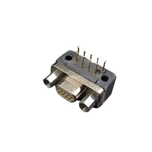
The product has the advantages of high density, lightweight and miniaturization, which can realize the reliable interconnection of the electrical circuit system from cable to cable, cable to printed board, and between printed board and printed board.
The product can withstand strong vibration, shock and other harsh operating environment, especially suitable for the use of space, equipment lightweight has special requirements for the use of the occasion.
THE J30J SERIES CONNECTOR FEATURES:
J30J series ordinary products: 21E0.204.118JT
J30JM series rubber seal products: Q/21EJ618
J30J series glass sintering seal products: Q/21EJ1001

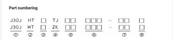 1 Principal:J30J
2 Shell structure and materials:Electroless nickel plating on aluminum alloy,Casing flflange hole diameter (9-69 core is 02.31,100 core is 3.7)
3 Number of contacts:9,15,21,25,31,37,A51,51,69 ,100
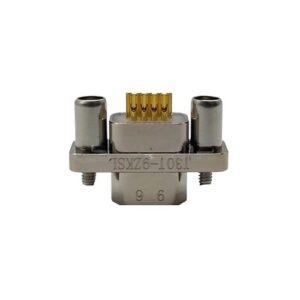
4 Connector and contact parts type:TJ- Plug insert pin; ZK- Socket with jack
5 Form of the end of the contact:
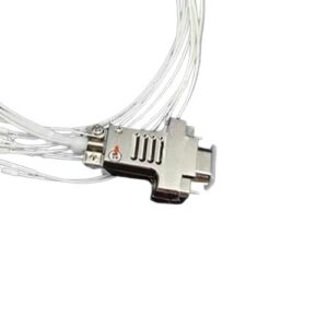
Type I: 00- Sling type, crimping wire wire gauge AWG26 (wire brand, length on demand)
CA- Sling type, crimped C55/0112-26 conductor, sling length 450mm.
CB- Sling type, crimped C55/0112-26 conductor, sling length 900mm.
Type II: SA- welding cup type
ND — In-line printed board, pin length 2.77mm,9-37 core spacing 2.54mm
x row spacing 1.91mm. 51-100 core spacing 1.91mm x 1.91mm.
ND — In-line printed board, pin length 3.56mm,9-37 core spacing 2.54mm
x row spacing 1.91mm. 51-100 core spacing 1.91mm x 1.91mm.
ND — In-line printed board, pin length 4.37mm,9-37 core spacing 2.54mm
x row spacing 1.91mm. 51-100 core spacing 1.91mm x 1.91mm.
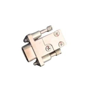
Type B – Free end locking assembly, thread #2-56UNC-2A, 100 cores for 9-69 cores
Use thread #4-40UNC-2A (refer to locking attachment in product family tree);
Type N – Free end locking assembly, thread #2-56UNC-2B, 100 cores for 9-69 cores
Use thread #4-40UNC-2B (refer to locking attachment in product family tree);
7 Tail cover accessories Category:
Type I: Not indicated – without tail cover attachment
Type II: With plastic tail cover attachment
SF has been inserted into the printed board, 9, 15, 21, 25, 31, 37 core pins for 4 rows.
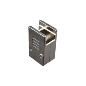
Type III: Accessories with metal tail cover (see product pedigree for details)
8 Plastic tail Cover Type:
Unsympathetic – No plastic tail cover
Type K – Through hole for mounting of tail cover (in-line printed board only)
The product has the advantages of high density, lightweight and miniaturization, which can realize the reliable interconnection of the electrical circuit system from cable to cable, cable to printed board, and between printed board and printed board.
The product can withstand strong vibration, shock and other harsh operating environment, especially suitable for the use of space, equipment lightweight has special requirements for the use of the occasion.
THE J30J SERIES CONNECTOR FEATURES:
J30J series ordinary products: 21E0.204.118JT
J30JM series rubber seal products: Q/21EJ618
J30J series glass sintering seal products: Q/21EJ1001
1 Principal:J30J
2 Shell structure and materials:Electroless nickel plating on aluminum alloy,Casing flflange hole diameter (9-69 core is 02.31,100 core is 3.7)
3 Number of contacts:9,15,21,25,31,37,A51,51,69 ,100
4 Connector and contact parts type:TJ- Plug insert pin; ZK- Socket with jack
5 Form of the end of the contact:
Type I: 00- Sling type, crimping wire wire gauge AWG26 (wire brand, length on demand)
CA- Sling type, crimped C55/0112-26 conductor, sling length 450mm.
CB- Sling type, crimped C55/0112-26 conductor, sling length 900mm.
Type II: SA- welding cup type
ND — In-line printed board, pin length 2.77mm,9-37 core spacing 2.54mm
x row spacing 1.91mm. 51-100 core spacing 1.91mm x 1.91mm.
ND — In-line printed board, pin length 3.56mm,9-37 core spacing 2.54mm
x row spacing 1.91mm. 51-100 core spacing 1.91mm x 1.91mm.
ND — In-line printed board, pin length 4.37mm,9-37 core spacing 2.54mm
x row spacing 1.91mm. 51-100 core spacing 1.91mm x 1.91mm.
Type B – Free end locking assembly, thread #2-56UNC-2A, 100 cores for 9-69 cores
Use thread #4-40UNC-2A (refer to locking attachment in product family tree);
Type N – Free end locking assembly, thread #2-56UNC-2B, 100 cores for 9-69 cores
Use thread #4-40UNC-2B (refer to locking attachment in product family tree);
7 Tail cover accessories Category:
Type I: Not indicated – without tail cover attachment
Type II: With plastic tail cover attachment
SF has been inserted into the printed board, 9, 15, 21, 25, 31, 37 core pins for 4 rows.
Type III: Accessories with metal tail cover (see product pedigree for details)
8 Plastic tail Cover Type:
Unsympathetic – No plastic tail cover
Type K – Through hole for mounting of tail cover (in-line printed board only)