| Parameter | Value |
|---|---|
| Ambient | -55 ~ +125°C |
| Contact resistance | ≤ 10Ω |
| Relative | +40°C attain 95% |
| Insulation resistance | ≥5000 Ω |
| Vibrate | 10~ 2000Hz 294m/s² |
| Mediator resistant oneself | 800V |
| Lash | 980m/s² |
| Mechanical life | 500 |
| Accelerated | 735m/s² |
| Instantaneous time | ≤1μs |
| Rated current | 3A |
| Salt fog time | 96h |
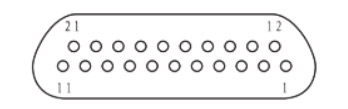
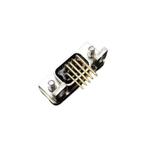
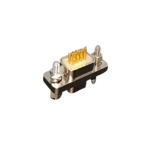
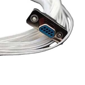
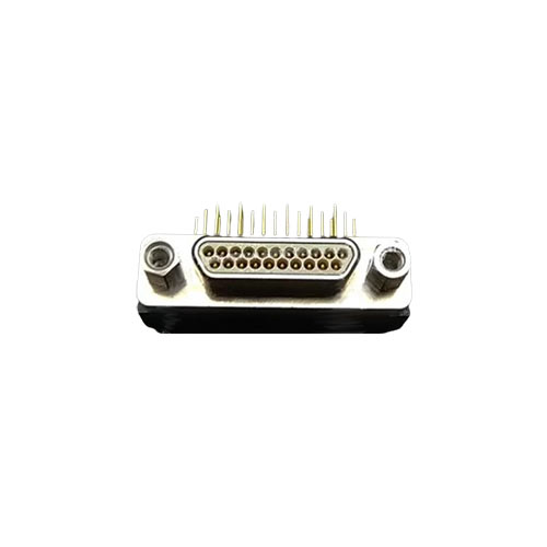
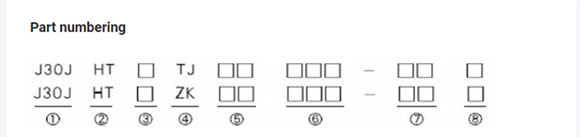 1 Principal:J30J2 Shell structure and materials:Electroless nickel plating on aluminum alloy,Casing flflange hole diameter (9-69 core is 02.31,100 core is 3.7)3 Number of contacts:9,15,21,25,31,37,A51,51,69 ,1004 Connector and contact parts type:TJ- Plug insert pin; ZK- Socket with jack
5 Form of the end of the contact:
Type I: 00- Sling type, crimping wire wire gauge AWG26 (wire brand, length on demand)
CA- Sling type, crimped C55/0112-26 conductor, sling length 450mm.
CB- Sling type, crimped C55/0112-26 conductor, sling length 900mm.
Type II: SA- welding cup type
ND — In-line printed board, pin length 2.77mm,9-37 core spacing 2.54mm
x row spacing 1.91mm. 51-100 core spacing 1.91mm x 1.91mm.
ND — In-line printed board, pin length 3.56mm,9-37 core spacing 2.54mm
x row spacing 1.91mm. 51-100 core spacing 1.91mm x 1.91mm.
ND — In-line printed board, pin length 4.37mm,9-37 core spacing 2.54mm
x row spacing 1.91mm. 51-100 core spacing 1.91mm x 1.91mm.
Use thread #4-40UNC-2B (refer to locking attachment in product family tree);
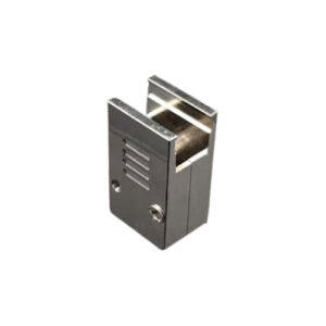
7 Tail cover accessories Category:
Type I: Not indicated – without tail cover attachment
Type II: With plastic tail cover attachment
SF has been inserted into the printed board, 9, 15, 21, 25, 31, 37 core pins for 4 rows.
Type III: Accessories with metal tail cover (see product pedigree for details)
8 Plastic tail Cover Type:
Unsympathetic – No plastic tail cover
Type K – Through hole for mounting of tail cover (in-line printed board only)
 1 Principal:J30J2 Shell structure and materials:Electroless nickel plating on aluminum alloy,Casing flflange hole diameter (9-69 core is 02.31,100 core is 3.7)3 Number of contacts:9,15,21,25,31,37,A51,51,69 ,1004 Connector and contact parts type:TJ- Plug insert pin; ZK- Socket with jack
5 Form of the end of the contact:
Type I: 00- Sling type, crimping wire wire gauge AWG26 (wire brand, length on demand)
CA- Sling type, crimped C55/0112-26 conductor, sling length 450mm.
CB- Sling type, crimped C55/0112-26 conductor, sling length 900mm.
Type II: SA- welding cup type
ND — In-line printed board, pin length 2.77mm,9-37 core spacing 2.54mm
x row spacing 1.91mm. 51-100 core spacing 1.91mm x 1.91mm.
ND — In-line printed board, pin length 3.56mm,9-37 core spacing 2.54mm
x row spacing 1.91mm. 51-100 core spacing 1.91mm x 1.91mm.
ND — In-line printed board, pin length 4.37mm,9-37 core spacing 2.54mm
x row spacing 1.91mm. 51-100 core spacing 1.91mm x 1.91mm.
Use thread #4-40UNC-2B (refer to locking attachment in product family tree);
7 Tail cover accessories Category:
Type I: Not indicated – without tail cover attachment
Type II: With plastic tail cover attachment
SF has been inserted into the printed board, 9, 15, 21, 25, 31, 37 core pins for 4 rows.
Type III: Accessories with metal tail cover (see product pedigree for details)
8 Plastic tail Cover Type:
Unsympathetic – No plastic tail cover
Type K – Through hole for mounting of tail cover (in-line printed board only)