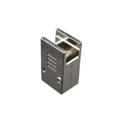
| Product Name | Backshell For J30J Series Connector | ||
|---|---|---|---|
| Application | Suitable For Wire Pressing And Welding Products | ||
| Materials | Aluminium | Quality | Well |
| Color | Silver | ||
| Highlight |
|
||
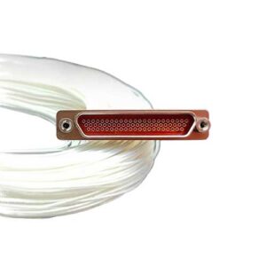
The product has the advantages of high density, lightweight and miniaturization, which can realize the reliable interconnection of the electrical circuit system from cable to cable, cable to printed board, and between printed board and printed board.
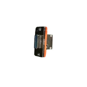
The product can withstand strong vibration, shock and other harsh operating environment, especially suitable for the use of space, equipment lightweight has special requirements for the use of the occasion
Conforms to GJB2446A (equivalent to MIL-C-83513)
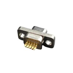
Male pin is twist pin
High-density contact, spacing 1.27mm
metal shield shell, equivalent to the American MDM series
There are 11 specifications including 9-144 cores
There are tail end changes that apply to the hole spacing of the printed board
Implement enterprise standards:
J30J series ordinary products: 21E0.204.118JT
J30JM series rubber seal products: Q/21EJ618
J30J series glass sintering seal products: Q/21EJ1001
| How to order: | ||||||||
|---|---|---|---|---|---|---|---|---|
| J30J | X | -X | ZK/TJ | X | X | -X | X | X |
| Basic series | ||||||||
| J30J – Basic type | ||||||||
| J30JC – Nickel copper plating (weldable) | ||||||||
| J30JS – Passivation of stainless steel (not weldable) | ||||||||
| Serial variant | ||||||||
| Unmarked: Basic type | ||||||||
| A: Quick lock | ||||||||
| E: The connector housing height is reduced from the basic type | ||||||||
| M: Rubber sealing product | ||||||||
| R: Contact pin, Jack are mounted in reverse | ||||||||
| Number of contacts: | ||||||||
| 9,15,21,25,31,37,51,66,74,100,144 Core | ||||||||
| Electrical connector type: | ||||||||
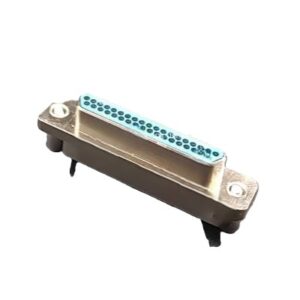
| ZK: The socket is equipped with a jack, TJ: The plug is inserted into a pin | ||||||||
| ZJ: The socket is equipped with a pin, TK: The plug is inserted into a jack | ||||||||
| Contact end form: | ||||||||
| No mark – Type of crimping | ||||||||
| S – Type of Welding | ||||||||
| N,N3,N8,N12 – Horizontal PCB model, the grid spacing of PCB is 2.54×2.54, in which type N is the basic type product | ||||||||
| W – 90° PCB model, the grid spacing of PCB is 2.54×2.54 | ||||||||
| Type of locking and mounting components: | ||||||||
| No mark – Default locking component (Type L with wire or welded plug, type P with wire or welded socket, type P7 with 90°PCB products and type P5 with horizontal PCB products) | ||||||||
| Y – No locking component is provided | ||||||||
| Common locking components – such as L, K, P, etc., see the locking component type and instructions | ||||||||
| Modified product identification (If it is multiple, write in alphabetical order, such as -AD, -JQ, etc.): | ||||||||
| A – The product conductor is covered with wave proof sleeve, and the tail has a clamping plate | ||||||||
| D – The shell is added with anti-rotating structure | ||||||||
| D2 – Screw compression spring and screw locking structure, plug matching clamp wire | ||||||||
| J – printed board grid spacing changed to 1.27×2.54 | ||||||||
| Q,Q8 – Shell flange is widened | ||||||||
| R4,Q4 – The locking structure adopts the spring fast locking structure | ||||||||
| Attachment identification: | ||||||||
| A1 – Tail clamp accessories (only suitable for wire pressing and welding products) | ||||||||
| A3 – Tail clamp accessories (only suitable for wire pressing and welding products) | ||||||||
| Specific requirements for conductors: | ||||||||
| Including wire cross-sectional area, color, length, external protection, etc., (Only suitable for pressed wire products) | ||||||||
The product has the advantages of high density, lightweight and miniaturization, which can realize the reliable interconnection of the electrical circuit system from cable to cable, cable to printed board, and between printed board and printed board.
The product can withstand strong vibration, shock and other harsh operating environment, especially suitable for the use of space, equipment lightweight has special requirements for the use of the occasion
Conforms to GJB2446A (equivalent to MIL-C-83513)
Male pin is twist pin
High-density contact, spacing 1.27mm
metal shield shell, equivalent to the American MDM series
There are 11 specifications including 9-144 cores
There are tail end changes that apply to the hole spacing of the printed board
Implement enterprise standards:
J30J series ordinary products: 21E0.204.118JT
J30JM series rubber seal products: Q/21EJ618
J30J series glass sintering seal products: Q/21EJ1001
| How to order: | ||||||||
|---|---|---|---|---|---|---|---|---|
| J30J | X | -X | ZK/TJ | X | X | -X | X | X |
| Basic series | ||||||||
| J30J – Basic type | ||||||||
| J30JC – Nickel copper plating (weldable) | ||||||||
| J30JS – Passivation of stainless steel (not weldable) | ||||||||
| Serial variant | ||||||||
| Unmarked: Basic type | ||||||||
| A: Quick lock | ||||||||
| E: The connector housing height is reduced from the basic type | ||||||||
| M: Rubber sealing product | ||||||||
| R: Contact pin, Jack are mounted in reverse | ||||||||
| Number of contacts: | ||||||||
| 9,15,21,25,31,37,51,66,74,100,144 Core | ||||||||
| Electrical connector type: | ||||||||
| ZK: The socket is equipped with a jack, TJ: The plug is inserted into a pin | ||||||||
| ZJ: The socket is equipped with a pin, TK: The plug is inserted into a jack | ||||||||
| Contact end form: | ||||||||
| No mark – Type of crimping | ||||||||
| S – Type of Welding | ||||||||
| N,N3,N8,N12 – Horizontal PCB model, the grid spacing of PCB is 2.54×2.54, in which type N is the basic type product | ||||||||
| W – 90° PCB model, the grid spacing of PCB is 2.54×2.54 | ||||||||
| Type of locking and mounting components: | ||||||||
| No mark – Default locking component (Type L with wire or welded plug, type P with wire or welded socket, type P7 with 90°PCB products and type P5 with horizontal PCB products) | ||||||||
| Y – No locking component is provided | ||||||||
| Common locking components – such as L, K, P, etc., see the locking component type and instructions | ||||||||
| Modified product identification (If it is multiple, write in alphabetical order, such as -AD, -JQ, etc.): | ||||||||
| A – The product conductor is covered with wave proof sleeve, and the tail has a clamping plate | ||||||||
| D – The shell is added with anti-rotating structure | ||||||||
| D2 – Screw compression spring and screw locking structure, plug matching clamp wire | ||||||||
| J – printed board grid spacing changed to 1.27×2.54 | ||||||||
| Q,Q8 – Shell flange is widened | ||||||||
| R4,Q4 – The locking structure adopts the spring fast locking structure | ||||||||
| Attachment identification: | ||||||||
| A1 – Tail clamp accessories (only suitable for wire pressing and welding products) | ||||||||
| A3 – Tail clamp accessories (only suitable for wire pressing and welding products) | ||||||||
| Specific requirements for conductors: | ||||||||
| Including wire cross-sectional area, color, length, external protection, etc., (Only suitable for pressed wire products) | ||||||||